
How to Read Superconducting Qubit Coherence Time
2026.10.14 · Blog superconducting qubit coherence time
There is no single "good" coherence time for a superconducting qubit. Before judging any number, ask three things: is it T1, T2* or T2 echo, is it an average or a best run, and over how long a window was it measured? Once those are clear, the landscape is easy to place. A well-made transmon sits in the tens to hundreds of microseconds. A tantalum-based transmon has shown time-averaged T1 above 0.3 ms in its best device, and fluxonium qubits have passed one millisecond in published work.
What Superconducting Qubit Coherence Time Looks Like Today
Coherence times have grown by roughly five orders of magnitude since 1998, mostly through better qubit designs and, more recently, materials work, according to a review on OSTI. For 2D transmons, T1 stayed near 100 µs for about a decade until tantalum replaced niobium in the capacitor pads. That change gave an average T1 of 0.23 ms across devices, with a best device at 0.36 ms.
Keep one caution in mind: published values are usually the best result from the best device. T1 also drifts, because defects at surfaces and interfaces move in and out of resonance with the qubit. A fair comparison uses time-averaged values over a stated window and, ideally, several qubits. If a number is described only as "up to," treat it as a ceiling.
T1, T2* and T2 Echo Are Not Interchangeable Coherence Times
Three measurements are routinely called "coherence time," and each answers a different question.
-
T1 is how long the qubit holds its energy.
-
T2* (Ramsey) is how long it keeps its phase when left alone. It is sensitive to slow frequency drift.
-
T2 echo adds a refocusing pulse that cancels slow noise, so it is usually longer than T2*.
A quick sanity check is that T2 cannot exceed 2 × T1. If a reported T2 is clearly above that, something is wrong with the data or the definition. The gap below that limit is also informative. In one flux-qubit experiment with T1 of 12 µs, up to 200 refocusing pulses lifted T2 to about 23 µs, close to the 2T1 ceiling and a 50-fold gain over the Ramsey value. So if your T2 is far below 2T1, control can help. If it is already near 2T1, only a better T1 will.
A large gap between T2* and T2 echo means low-frequency noise is present. Echo hides it, but your circuits will still feel it. Ask for all three numbers.
What Coherence Time Means for the Circuits You Want to Run
Take a 200 ns two-qubit gate on a qubit with T1 and T2 near 100 µs. One gate uses about 0.2% of the coherence time, so decoherence alone contributes an error on the order of 0.1% to 0.2% per gate. This is a rough order-of-magnitude guide, not a performance guarantee. Control errors, crosstalk and readout errors add to it, so coherence time should always be read next to gate and readout fidelity measured on the same device.
When Superconducting Qubit Coherence Time Comes In Lower Than Expected
Low or unstable numbers are common. The causes below run from cheap checks to expensive ones.
Defects and drift. Tiny defects at electrode interfaces can absorb energy from the qubit, which is one reason T1 jumps between runs. Tuning them away with a DC electric field raised the 30-minute average T1 by 23% in one study. You do not need that setup to learn from it: repeat T1 over several hours and you will see whether the problem is fluctuation or steady loss.
Quasiparticles and shielding. Stray radiation creates unpaired electrons that shorten T1. In one experiment, removing quasiparticles cut their density by 70% and improved relaxation about threefold. If T1 improves after you fix infrared or magnetic shielding, this is the likely cause.
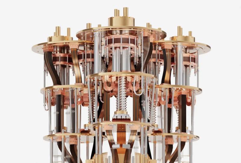
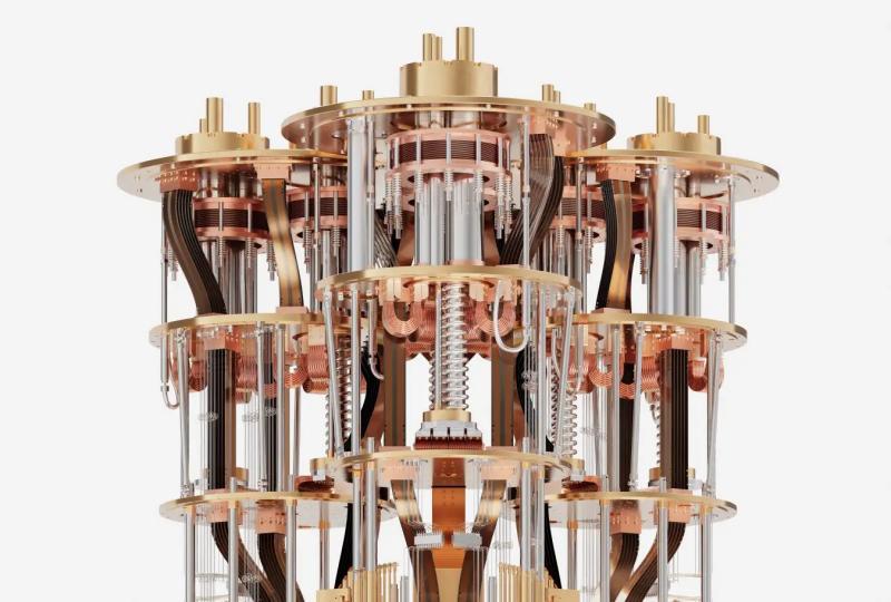
Thermalization and wiring. A poorly thermalized chip, or lines that carry heat and noise to the base stage, will limit coherence however good the chip is. Check base-temperature stability, attenuator and filter anchoring, and sample-box grounding. The cryogenic stack for superconducting qubits is often treated as background infrastructure, but it is one of the first places to look.
Control noise and frequency drift. Noise on control and flux lines turns directly into dephasing. Stabilizing qubit frequency with feedback raised T2 from 6.2 to 7.7 µs, a 26% gain. If T2* is poor but T2 echo is fine, review the qubit measurement and control electronics first.
A practical order of checks:
-
Repeat T1, T2* and T2 echo over a few hours and look at the spread.
-
Compare T2 with 2 × T1.
-
Check shielding and base-stage stability.
-
Review filtering and thermal anchoring on every line.
-
Only then look at the chip: surfaces, materials and fabrication.
Practical Ways to Extend Superconducting Qubit Coherence Time
Most remaining loss in a good transmon comes from surfaces and interfaces rather than the bulk, so the biggest gains usually come from the chip side: cleaner interfaces, better materials such as tantalum, and layouts that keep electric fields away from lossy surfaces. These are fabrication-stage choices, so a team without its own fab depends largely on its chip supplier for them.
On the control side, echo and multi-pulse sequences are cheap to try, but they help only with dephasing. They improve T2, never T1, and each extra pulse adds gate time and pulse error, so more pulses is not always better. On the environment side, a cryostat with a steady base temperature, low vibration and a well-shielded sample space keeps coherence stable. For many teams, stability over weeks matters more than a record on one good day.
How to Read Superconducting Qubit Coherence Time in a System Specification
If you are evaluating a system rather than building one, a datasheet number is only useful with context. Ask:
-
Which of T1, T2* and T2 echo is quoted?
-
Is it a mean, median or best value, over how many qubits and what time window?
-
Was it measured on the delivered chip in the delivered cryostat, or on a test setup?
-
How consistent are chips from the same batch, and how is drift handled over weeks?
These questions fit naturally into a staged evaluation of superconducting quantum computers, where a pilot or remote-access phase lets you check numbers yourself before committing.
A coherence value belongs to the whole stack, not the chip alone. The same chip can show different T1 and T2 under different filtering, control noise and thermal conditions. That is why the SPINQ QPU C Series chips (QPU C25, C20, C10 and C2), which are superconducting processors for research and system integration, are best assessed together with the SPINQ QCM control and measurement system and Cryogenic Environment Deployment Services. Ask for characterization data on the exact combination you plan to run, not the chip in isolation.
Conclusion: Trust a Superconducting Qubit Coherence Time Only When You Can Trace It
A coherence time is only as useful as the context around it. Before you rely on any number, confirm which time it is, whether it is an average or a best run, and whether T2 sits sensibly below 2 × T1. Then check that it was measured on hardware and in a setup comparable to yours, alongside gate and readout fidelity. If a number comes with clear answers to those questions, it is worth planning around. If not, treat it as a hint and measure it yourself.
.jpg)
Featured Content